An advanced 2m ARDF-Receiver by DF1FO
Overview
This paper describes a microprocessor-controlled 2m-ARDF-receiver. The receiver is considerably more complex than most of the simple ARDF-receivers from Eastern Europe or China. In return it offers many advance features:
Highlights
- High sensitivity
- Narrow crystal-filter for good selectivity
- PLL-controlled frequency
- Stores up to 4 frequencies
- Instantaneous S-Meter with Peak-Hold
- Acoustical S-Meter
- Attenuator with calibrated 5dB steps from 0 to 120 dB
- Automatic Attenuation when S-Meter reaches full-scale
- User interface: rotary encoder and 2*8 Character LCD
- Estimation of distance to transmitter
- Display of current fox and remaining transmit time
- Warning n seconds before end of fox transmit time
- Stopwatch shows elapsed time
- Display of battery voltage, low voltage warning
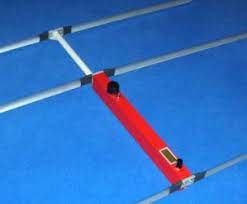
Receiver with 3-Element-Yagi
Circuit Description
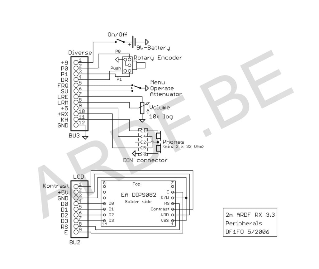
Refer to the schematics on the following two pages.
The analogue part of the receiver is a double conversion receiver with 10,7 MHz and 455 kHz intermediate frequencies and an AM-demodulator.
The antenna signal is amplified by the preamp T1. The preamp is turned off for strong input signals, this reduces the signal level by about 40 dB. T2 is the first mixer and oscillator. Its frequency is 10,7 MHz below the input frequency and controlled by the PLL-circuit TSA6057. The PLL has a frequency resolution of 1,25 kHz. The cascaded crystal filters QF1/QF2 are responsible for most of the selectivity of the receiver..
Next is an AM-receiver circuit TCA440. It contains the 10,7 MHz IF-amplifier, crystal controlled 2nd oscillator, 2nd mixer, and the 455 kHz IF-amplifier. The gain of the TCA440 can be controlled over a range of more than 100 dB. The output signal of the AM demodulator D2 contains an AC-component, the modulation, and a DC-component proportional to the level of the input signal.
The AF-amplifier LM386 drives a headphone of medium to high impedance.
The circuitry around the processor Atmel ATMega 8-16 is harder to understand and will therefore be described more detailed.
The processor clock is set by Q2 to 5 MHz. The processors clock signal is also used as reference clock for the PLL.
Pin PC0 turns the preamp on or off (Pin is low resp high-Z).
Pins PC4 and PC5 drive the I2C-Bus to the PLL. PC4 is also used to detect if the receiver is on.
Pins PC1 and PC2 are analogue inputs. They are used to measure the battery voltage and the DC-Signal from the demodulator.
Pin PB3 is the (analogue) output of a pulsewidth-modulator. It controls the gain of the TCA440.
Pin PB1 is the output of a programmable oscillator, that generates the AF-signal for the acoustical S-meter and other tone signals. This signal is combined with the AF-signal from the demodulator.
Pin PB2 is normally high-Z. However when the acoustical S-Meter is on PB2 goes to low-Z and mutes the demodulator output through C46.
The receiver is controlled through a rotary encoder on pins PB0, PB4 and PC3, and a 3-position switch on Pins PD6 and PD7. The LC-Display with 2*8 characters is controlled by Pins PD0-PD5.
Finally the processor is connected to a 10-pin standard Atmel ISP connector for ‘In System Programming’.
The close proximity of a very sensitive receiver and the processor results in some ‘digital’ noise in the receiver. However this noise is very weak and can be heard only at minimum attenuation, therefore it does not limit the capabilities of the receiver. The only exception is the 29th harmonic of the 5 MHz crystal at 145,000 MHz. It makes the receiver less sensitive at this frequency. This is not a problem in Region 1, because this is a repeater input frequency and not used for foxhunts.
Another effect worth mentioning is that the PLL briefly unlocks when the frequency is changed. This makes searching for a (unknown) fox frequency a bit slow. Again not a big problem, because normally the frequencies are known.

Translation of some key words in the schematic:
Vorstufe Ein/Aus Preamp on/off
Regelspannung Gain control
NF-Verstärker AF amplifier
Notes:
The On/Off-switch can be combined with the volume control pot.
Menu/Operate/Attenuator is a 3-position toggle switch, the Attenuator-position is momentary and returns to Operate.
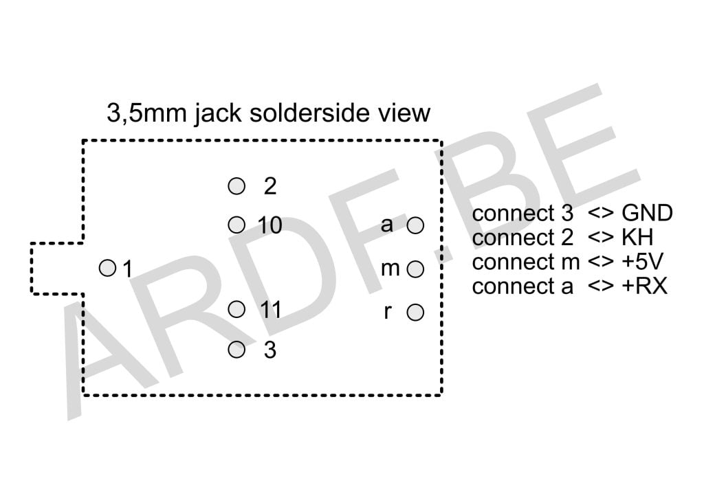
For headphones with 3,5mm-plug I have special jacks with an isolated switch:
Specifications
Measured with Rohde&Schwarz SMS2 at 144,525 MHz, 80% AM 1kHz
Frequency Range 143,9 – 146,1 MHz (optional 143,9 – 148,1 MHz)
Input Impedance 52 Ohm unbalanced
Sensitivity for 6 dB S+N/N 100 nV
Input Signal for 75% S-Meter-Indication 300nV – 300 mV
Attenuator Range 120 dB in 5 dB-Steps
Bandwidth +/- 7 kHz for –3 dB, +/-20 kHz for –40 dB
Mirror frequency rejection @ – 2 * 10,7 MHz >50 dB, @ – 2 * 455 kHz >70 dB
Operating Voltage 5,5 – 10 V
Operating Current 55 mA
Total cost of material w/o Antenna about 120 €
Operation
The On/Off-switch is combined with the volume control pot. Volume is normally set to a middle position and remains there until the receiver is switched off. When the receiver is turned on the stopwatch starts at 0 and the foxtimer with fox # 1, and the active frequency is loaded. The actual receiver (the analogue part) is powered only when the headphone is plugged in. Pulling the headphone reduces power consumption to 10 mA while keeping all timers and settings active.
The receiver is controlled by a rotary encoder and a toggle switch with the three positions Attenuator-Operate-Menu.
Switch in Operate Position
The LCD shows the number of the current fox, its remaining transmit time in seconds, the estimated distance to the fox and a 32-step bar-S-Meter. One to four dots in character position 2 show the selected frequency number, and an asterisk in position 5 indicates that the automatic Attenuator is off.
- Turning the encoder sets the attenuation in 5 dB-steps. When the signal reaches full-scale on the S-Meter, attenuation will automatically increase 5 dB. This is indicated by a tone signal. A reduction of the attenuation must always be done manually, by turning the encoder or clicking the toggle switch.
- A click on the encoder switches the audio signal between normal reception and acoustical S-Meter.
- Pushing and turning the encoder switches between the (up to 4) stored frequencies.
- A click of the toggle switch to the attenuator position opens the attenuator to the 40/10/0 dB position
- Pressing the switch for 1 s turns the automatic attenuator on/off.
An alarm sounds at a set time (e.g. 10 s) before the end of transmission of each fox.
When the battery voltage is low, another alarm will sound 10 sec after the start of transmission of fox 1.
Switch in Menu Position
After switching to Menu the display will show for a few seconds the current frequency, the stopwatch and the battery voltage. Turning the encoder selects one of four menu items: entering the up to four frequencies, starting/stopping the stopwatch, starting the foxtimer, and starting the setup-menu. Both menus and the frequency entry mode are left by setting the switch from the Menu position back to Operate.
The table on the following page shows all menu items and related operations. For a deeper insight into how to use all these functions: just play with the receiver.
Once you are on the run all settings in the menus have been done and you will stay in the ‘Operate’-mode. As you get closer to a transmitter the attenuator will automatically decrease receiver sensitivity. Just run for the maximum. The display shows S-meter, estimated distance to transmitter, # of current fox and remaining transmission time. The only adjustment you have to do is to open the attenuator when you need more sensitivity. This can be done in small steps by turning the encoder, or in big steps by clicking the attenuator switch.
Calibration Menu
There is one more menu: the Calibration menu. It allows to adapt the processor to the receiver hardware and some user preferences. It is started by putting the switch to Menu and pressing the rotary encoder while the receiver is switched on.
It offers the following functions:
- Select Language Deutsch/English/Nederlands
- Reset EEPROM to standard values.
- Calibrate battery voltage measurement
- Calibrate receiver frequency
- Calibrate attenuator in 13 steps 0..120 dB
- Select frequency range 144-146 (IARU Region 1) or 144-148 (Region 2,3)
- Select low battery warning threshold 5,8 – 8,0 V
- Calibrate distance estimation –5..+5
- Save changed data to EEPROM. All changed parameters must be saved with this function!
The calibration menu is left by switching to Operate.
Operation Overview
| Switch Position | Function | Display |
| Operate | < > Attenuator +/- 5 dB * Acoust. S-Meter On/Off <<*>> Frequency No. +/- Push and turn at least 2 steps within 0,5 sec a Open Attenuator to 40/10/0 dB A Auto-Attenuator On/Off | Fox-Timer Distance S-Meter 1-4 Dots: Frequency No. * = Auto-Attenuator Off |
| Menu | < > Select Item | Frequency Stop-Watch Battery-Voltage. |
Main Menu
| Menu Item | Function | |
| Change Freq. | * Start ==> | < > Freq. +/- 10 kHz <*> Freq. +/- 1,25 kHz * Next Freq. No If the fox uses FM (rather than AM) set the receiver 5-6kHz above or below the nominal frequency |
| ClkStop/Start | * Stop-Watch Stop / Reset and Start | |
| ClrTimer | * Restart Fox-Timer <*> Change current Fox-# Restart Timer at start of transmission of any fox with *, then set current fox # with <*> | |
| Setup menu | * Start Setup Menu ==> | * Start Setup Menu ==> < > Select Menu Item |
Setup Menu
| N Foxes | <*> # of Foxes 1..10, set to 1 for Foxoring Nfoxes=1’ = special mode for Foxoring: Fox-Timer is off, Alarm is off, display shows stopwatch |
| T Fox sec | <*> Fox Transmission Time 1..99 sec |
| T Fox msec | <*> Fox Transmission Time +/- 20 msec |
| P Fox | <*> Fox Output Power 1 µW – 30 W, dB only ‚dB only’ = no distance estimation, display shows attenuator dBs only |
| N Freq. | <*> # of frequencies used 1..4, special modes 12<>3, 1×2<>3 Special modes for foxhunts with two sets of foxes: Mode 12<>3 : 3 frequencies <* switches between Frq.1 and Frq.2, *> switches to Frq.3 Mode 1×2<>3 : the same, but receiver stores and recalls selected Frq.1/2 for each fox |
| T Alarm | <*> Alarmtime 1 – 30 sec before End, 0 = Off |
| Acoust. SM over | <*> Threshold 0/8 – 3/8, 0/8 = Acoust. SM always on Acoustical S-meter goes off, when the bar-S-meter is below the threshold for 3 sec. |
A few Notes on the Software
The receiver software is programmed in Assembler. It uses most of the 4096 words of the processors program memory. Only one interrupt is used, a 320 µs Timer. The interrupt handler serves the stopwatch and foxtimer and debounces the switch and encoder. All other functions are implemented on the main program level.
The LCD is loaded every 100 msec. If the LCD bus wiring is to close to the volume control wiring you will hear some 10Hz noise.
The DC voltage from the demodulator (= signal strength indication) is read in permanently. For the Bar-S-Meter the peak value of the last 300 msec is used to give a fairly stable indication. For the acoustical S-Meter the momentary value is used. Therefore finding the maximum is faster with the acoustical S-Meter.
The automatic attenuator reduces the attenuation by 5 dB when the S-Meter reaches full-scale (by 10 dB if it reaches 2 x full-scale). This is indicated by a 500/1000Hz double-tone. The receiver then waits for 200 msec for the effect of the new attenuator setting, before it increases attenuation by another 5 dB, if necessary. Increasing attenuation over the full dynamic range of 120db takes 12 * 200msec = 2,4 sec. In such a case turn the encoder to the right to speed things up.
The gain control voltage for the TCA440 is generated by a pulse width modulator. The right setting of the PWM for the 25 attenuator positions are found during the receiver calibration and stored in the processors EEPROM. To make the calibration easier only the n*10dB values are stored, the intermediate x5dB values are interpolated. The preamplifier T1 is turned off for attenuation values over 60dB. This reduces the signal level at the mixer by about 40 dB, and is compensated by increasing the gain of the TCA440.
The estimation of the distance to the fox is based on the following empirical data: a typical 1W fox in 100m distance gives a 3 mV signal from an HB9CV or 3 element antenna. As you get closer to the fox the signal increases by 20dB per 0,1x distance. Above 100m the signal decreases by 30db (!) per 10x distance. Above 1,5 km the variance of signal strength becomes too large to make a useful estimation. In this case the receiver will show the attenuator setting in dB instead of a distance estimation.
Any experienced foxhunter knows, that in real life the signal strength will seldom follow this ‘standard profile’. A mountain between receiver and fox decreases the signal strength considerably, a valley increases it. Still the experience of many foxhunters is, that an indication of ‘100m’ is much more meaningful than ‘80dB’.
By changing the PFox value in the setup-menu the receiver can be adapted to foxes of different strengths. I mostly use the 1 W setting. If your distance readings are mostly to close (to far), increase (reduce) the PFox value.
 Aan het laden…
Aan het laden…
Aan het laden…